
ATS-KA350 Advanced Training System
Product Price: USD $0.00 (INR ₹0.00)
ATS-KA350 Advanced Training System


|
|
||||||||||||||||||||
ATS-A320
|
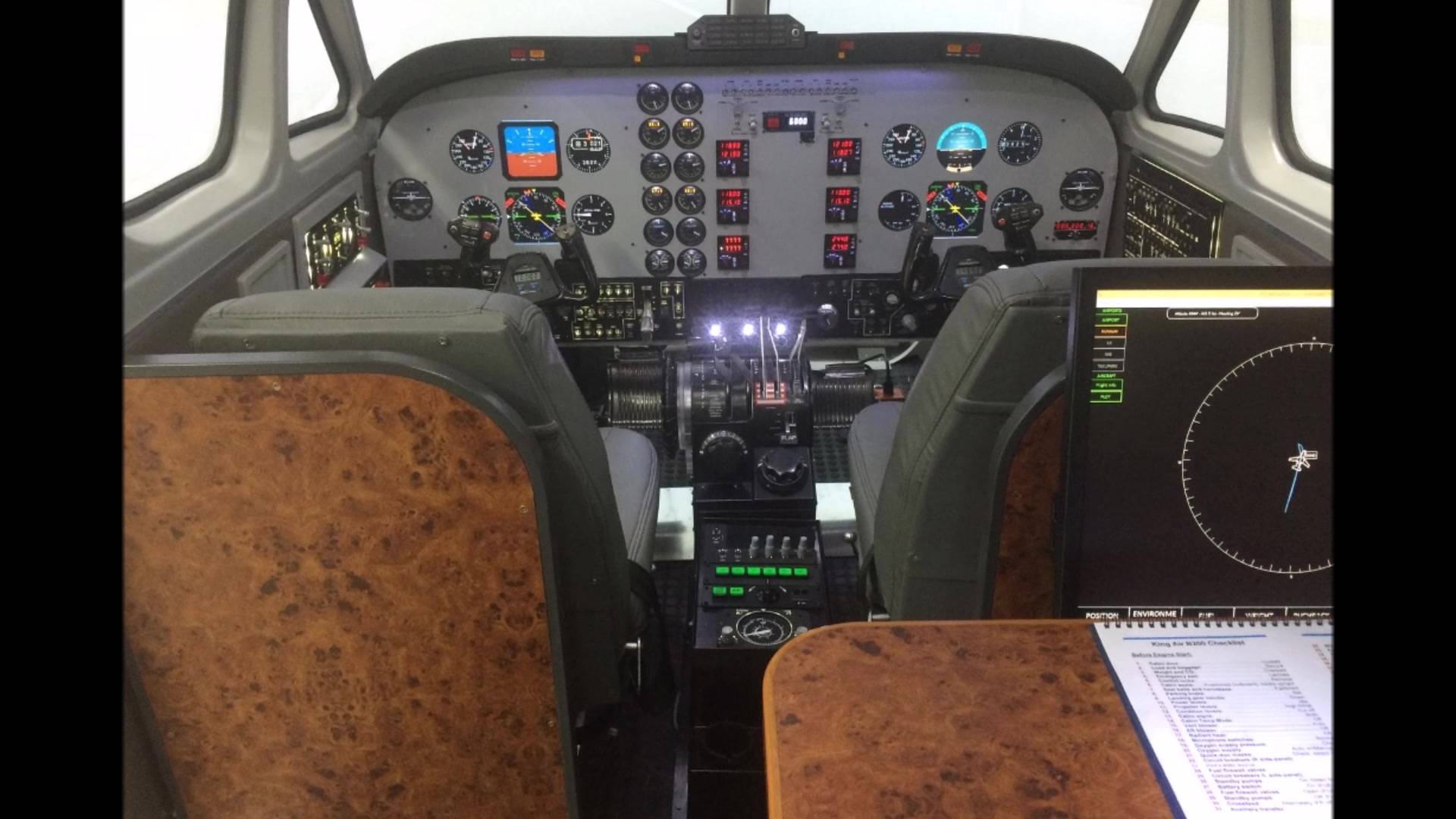
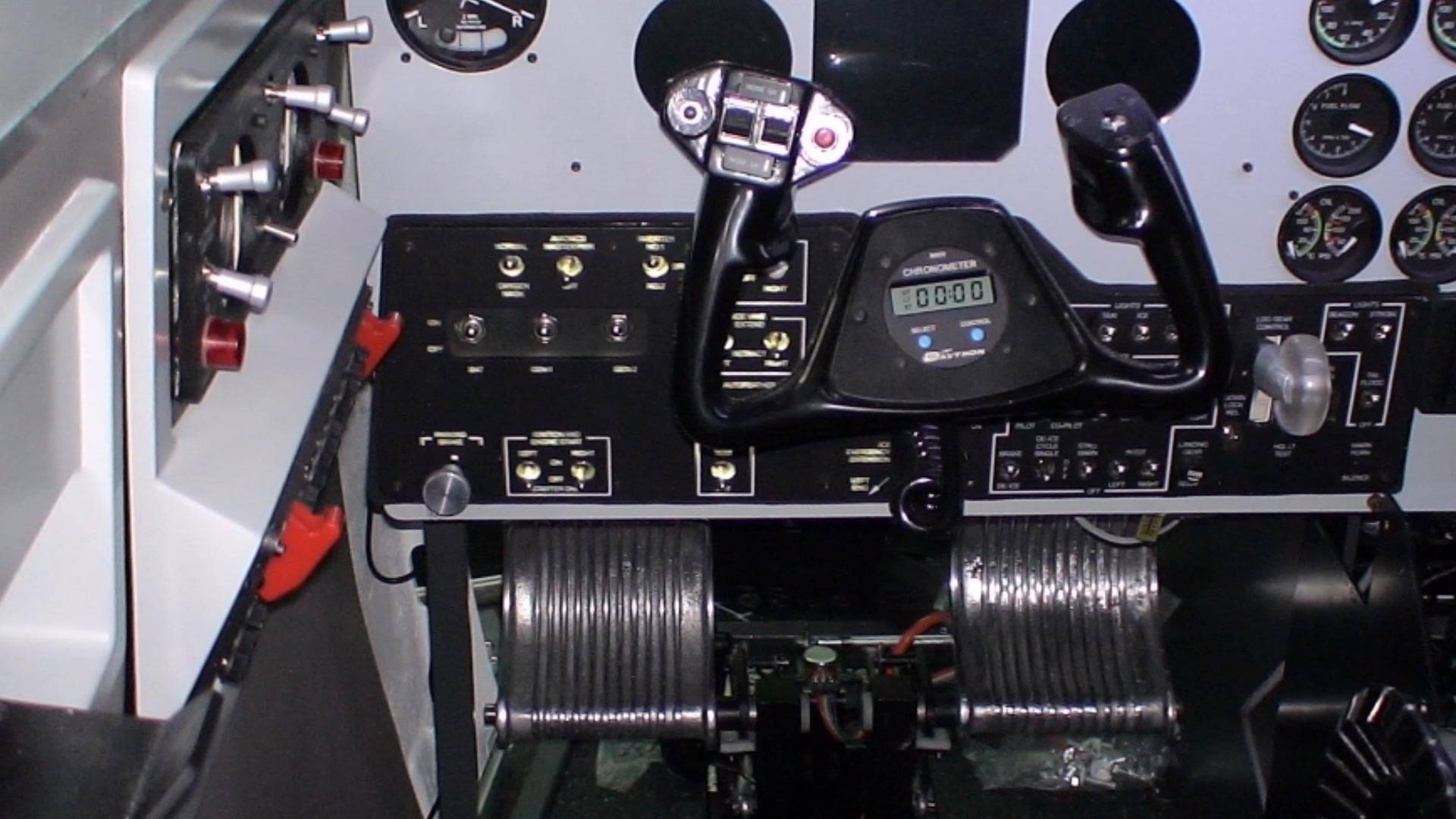
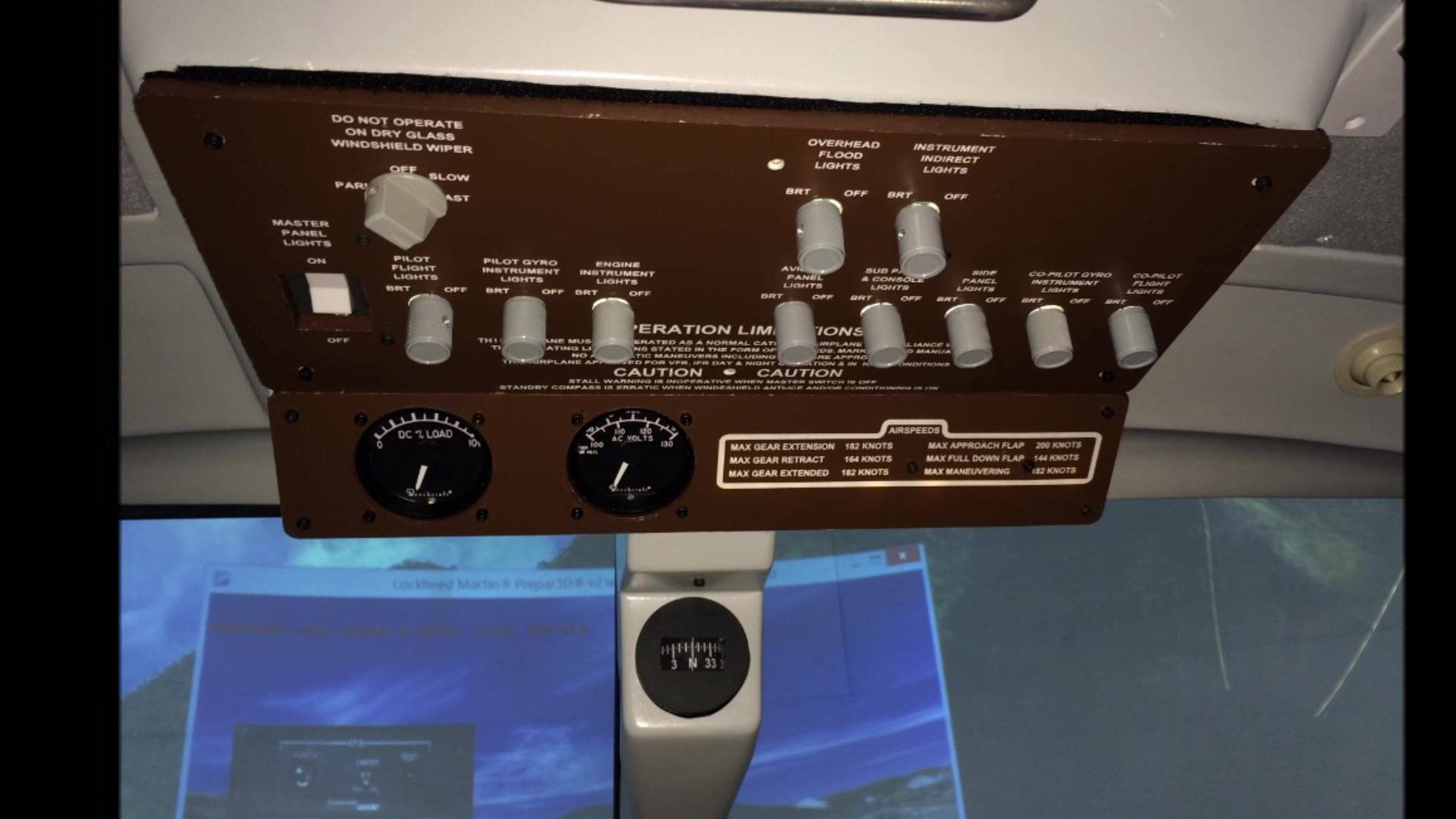
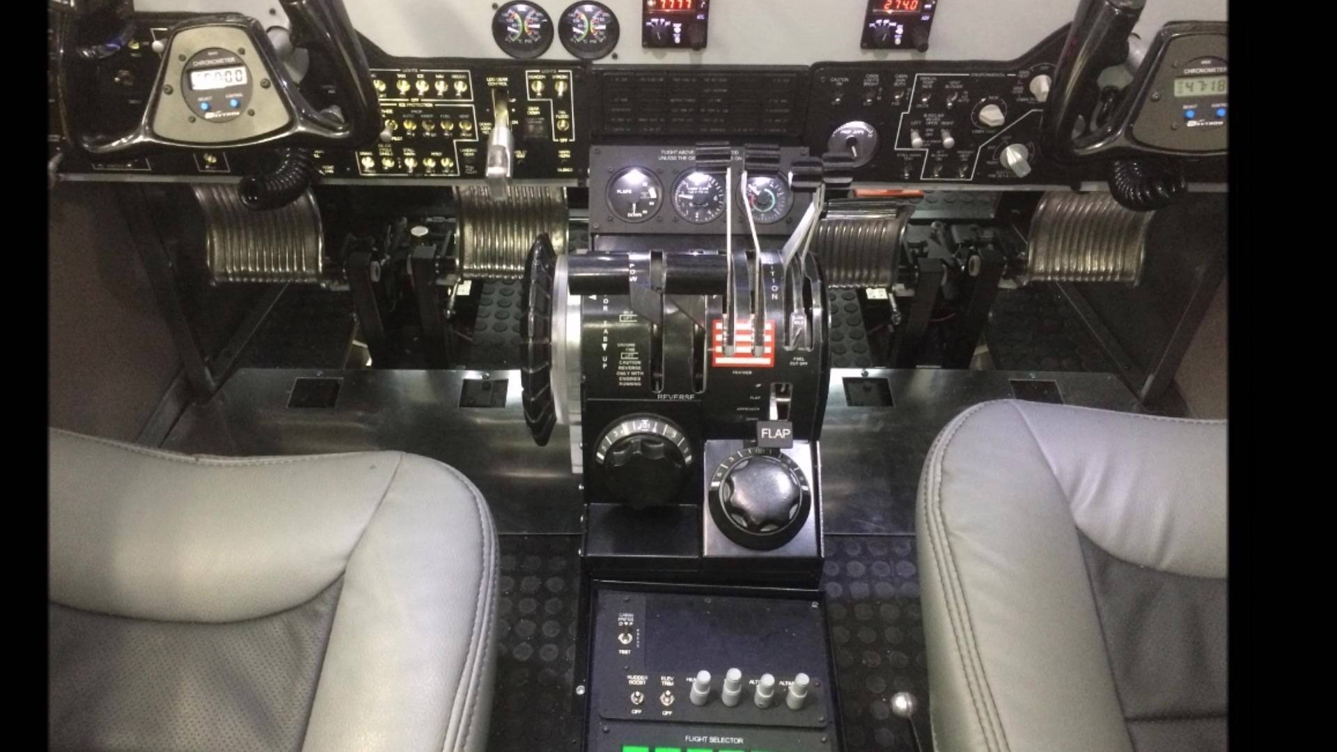
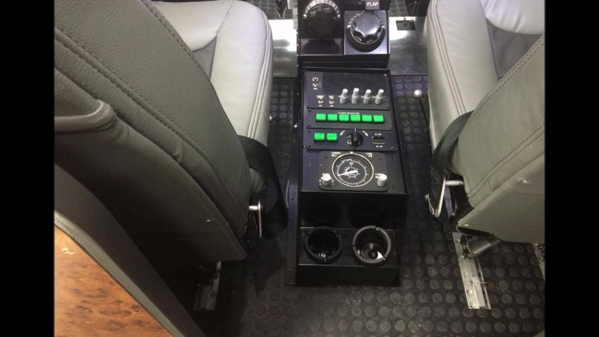
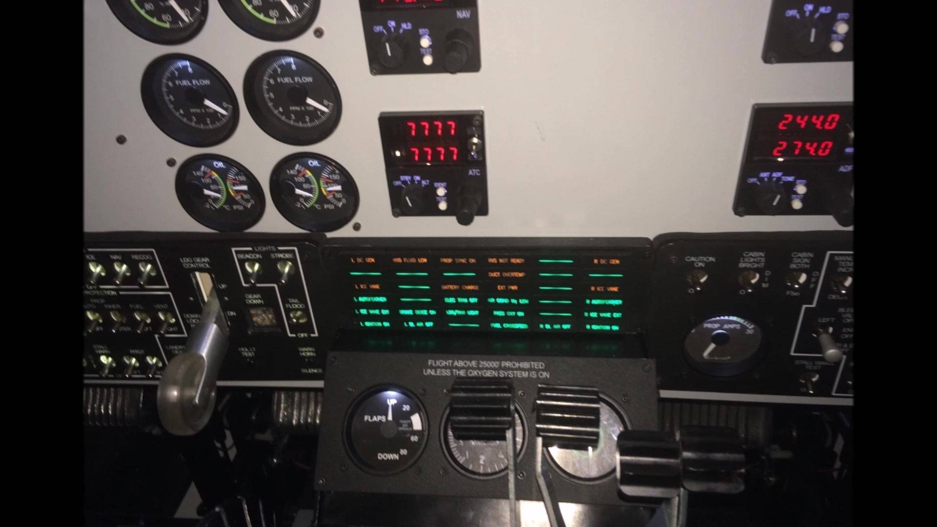
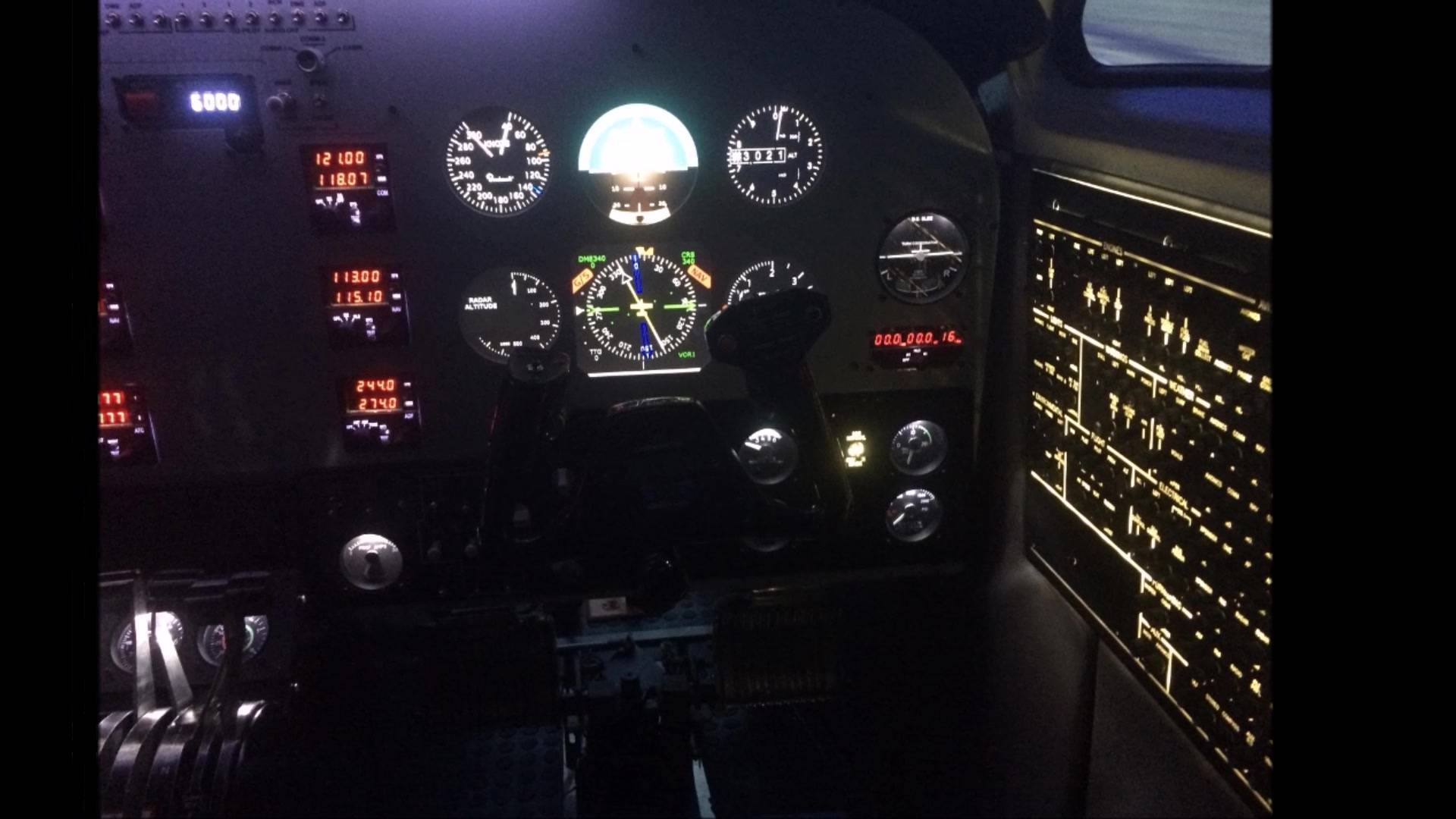
 Detailed replica of the aircraft cockpit.
